Amptek-si-pin: Difference between revisions
Jump to navigation
Jump to search
Created page with "== Amptek Si-pin == This data is just for reference, and here is a picture of the device with bond \ wires attached to a pcb for testing purposes. image:ampteksipin.jpg" |
No edit summary |
||
| Line 1: | Line 1: | ||
== Amptek Si-pin == | == Amptek Si-pin == | ||
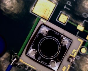
This data is just for reference, and here is a picture of the device with bond \ wires attached to a pcb for testing purposes. | This data is just for reference, and here is a picture of the device with bond \ | ||
wires attached to a pcb for testing purposes. | |||
[[file:ampteksipin.jpeg|thumb|border|Closeup mounted]] | |||
Next I collected V-I data on this detector: | |||
Data acquired on 6/10/2014 using bench supplies at room temp: | |||
{| align="center boarder = "1" | |||
! Voltage (no load, V) | |||
! Voltage (diode load, V) | |||
! Current (measured, uA) | |||
|- | |||
! Reverse bias | |||
|- | |||
| 10 || 5.7 | |||
|- | |||
| 20 || 5.8 | |||
|- | |||
| 30 || 5.9 | |||
|- | |||
| 40 || 6.0 | |||
|- | |||
| 50 || 6.0 | |||
|- | |||
| 60 || 6.1 | |||
|- | |||
| 70 || 6.1 | |||
|- | |||
| 80 || 6.2 | |||
|- | |||
| 90 || 6.2 | |||
|- | |||
| 100 || 6.3 | |||
|- | |||
| 110 || 6.3 | |||
|- | |||
| 120 || 6.3 | |||
|- | |||
| 130 || 6.4 | |||
|- | |||
| 140 || 6.4 | |||
|- | |||
| 150 || 6.4 | |||
|- | |||
| 160 || 6.4 | |||
|- | |||
| 170 || 6.5 | |||
|- | |||
| 180 || 6.5 | |||
|- | |||
| 190 || 6.5 | |||
|- | |||
| 200 || 6.5 | |||
|- | |||
| 210 || 6.6 | |||
|- | |||
| 220 || 6.6 | |||
|- | |||
| 230 || 6.6 | |||
|- | |||
| 240 || 6.7 | |||
|- | |||
| 250 || 6.7 | |||
|- | |||
| 260 || 6.7 | |||
|- | |||
| 270 || 6.7 | |||
|- | |||
| 280 || 6.8 | |||
|- | |||
| 290 || 6.8 | |||
|- | |||
| 300 || 6.9 | |||
|} | |||
Data acquired on 6/10/2014 using bench supplies at room temp: | |||
{| align="center boarder = "1" | |||
! Voltage (no load, V) | |||
! Voltage (diode load, V) | |||
! Current (measured, uA) | |||
|- | |||
! Reverse bias | |||
|- | |||
| 0.1 || 4.9 | |||
|- | |||
| 0.2 || 4.0 | |||
|- | |||
| 0.3 || 3.8 | |||
|- | |||
| 0.4 || 23.6 | |||
|- | |||
| 0.5 || 35.4 | |||
|- | |||
| 0.6 || 60.0 | |||
|- | |||
| 0.7 || 73.0 | |||
|- | |||
| 0.8 || 102 | |||
|- | |||
| 0.9 || 112 | |||
|- | |||
| 1.0 || 127 | |||
|- | |||
| 1.1 || 153 | |||
|- | |||
| 1.2 || 181 | |||
|} | |||
Latest revision as of 16:23, 21 March 2023
Amptek Si-pin[edit | edit source]
This data is just for reference, and here is a picture of the device with bond \ wires attached to a pcb for testing purposes.

Next I collected V-I data on this detector:
Data acquired on 6/10/2014 using bench supplies at room temp:
| Voltage (no load, V) | Voltage (diode load, V) | Current (measured, uA) |
|---|---|---|
| Reverse bias | ||
| 10 | 5.7 | |
| 20 | 5.8 | |
| 30 | 5.9 | |
| 40 | 6.0 | |
| 50 | 6.0 | |
| 60 | 6.1 | |
| 70 | 6.1 | |
| 80 | 6.2 | |
| 90 | 6.2 | |
| 100 | 6.3 | |
| 110 | 6.3 | |
| 120 | 6.3 | |
| 130 | 6.4 | |
| 140 | 6.4 | |
| 150 | 6.4 | |
| 160 | 6.4 | |
| 170 | 6.5 | |
| 180 | 6.5 | |
| 190 | 6.5 | |
| 200 | 6.5 | |
| 210 | 6.6 | |
| 220 | 6.6 | |
| 230 | 6.6 | |
| 240 | 6.7 | |
| 250 | 6.7 | |
| 260 | 6.7 | |
| 270 | 6.7 | |
| 280 | 6.8 | |
| 290 | 6.8 | |
| 300 | 6.9 |
Data acquired on 6/10/2014 using bench supplies at room temp:
| Voltage (no load, V) | Voltage (diode load, V) | Current (measured, uA) |
|---|---|---|
| Reverse bias | ||
| 0.1 | 4.9 | |
| 0.2 | 4.0 | |
| 0.3 | 3.8 | |
| 0.4 | 23.6 | |
| 0.5 | 35.4 | |
| 0.6 | 60.0 | |
| 0.7 | 73.0 | |
| 0.8 | 102 | |
| 0.9 | 112 | |
| 1.0 | 127 | |
| 1.1 | 153 | |
| 1.2 | 181 |